- All
- Product Name
- Product Keyword
- Product Model
- Product Summary
- Product Description
- Multi Field Search
 |


| Quantity: | |
|---|---|
DC24RT100BL
Keya
DC24RT100BL
DC-4Q Braking-Reversible, DC controller, DC24RT100BL
This reversible dc controller has quickly dynamic response, smooth operating, works well and perfect functions. FOUR QUADRANT REGENERATIVE OPERATION
| Model | DC24RT100BL |
| Volt | 24VDC |
| Rated Continuous Current | 70A |
| Max current | 100A |
| Control Mode | 0-5V,PWM |
| Soft start time | 0.2-20S |
| Soft stop time | 0.2-20S |
| Tempreture | -10℃ - 60℃ |
| Protection grade | IP20 |
| Weight | 1.5kg |
| Dimension | 212*115*63mm |
| Suitalbe | PM Brush dc motor |
| Application | Electric vehicle,stereo garage,flaw detector |
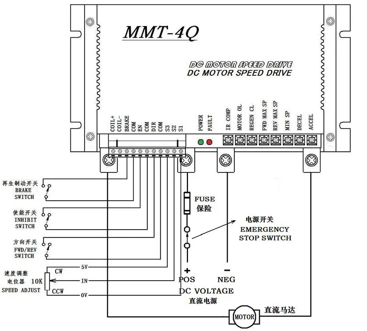
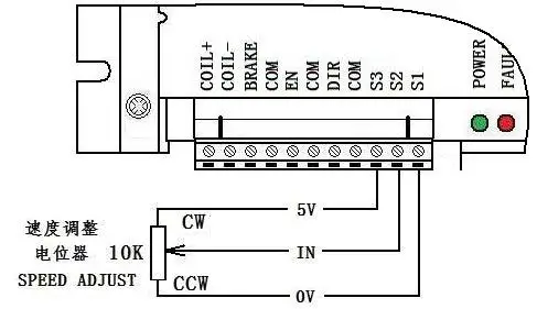
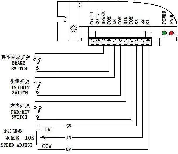
Connection about speed control potentiometer:
The operation of speed control potentiometers should follow above instructions in below Figure. Fit 10K regulator potentiometer between 5V, IN and 0V.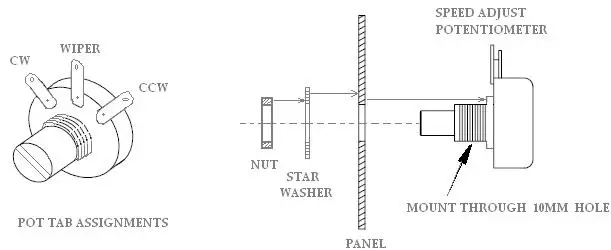
Caution:
The connecting wire of speed control potentiometer should be away from conductors of power input terminal and output in sake for reducing unnecessary interfere of electronic signals. The length of connecting wire should be shorten as far as possible. If the length is over 0.5m, the shielding wire is recommended.
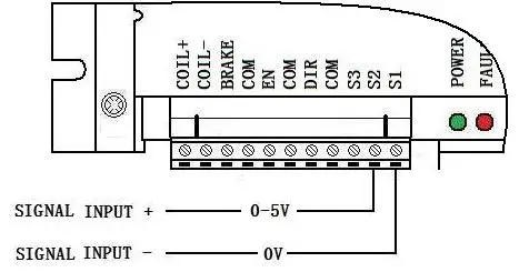
You also can control the motor speed by analog signal 0-5V, connect drawing as below:
Function and connection about control terminal:
Notice:
Connecting wires of speed control terminals should be away from conductors of power input terminal and output in sake for reducing unnecessary interfere of electronic signals. The length of connecting wire should be shorten as far as possible. If the length is over 0.5m, the shielding wire is recommended.
BRAKE:
Regenerative braking control: When quick stopping of motor is required, this function is suitable. Close brake switch, motor controller rapidly brakes motor’s speed by the way of regenerative braking then make motor stop immediately.
EN:
Enable control: Control the start and stop of motor
Open external enable switch, motor controller will automatically lock in internal circuit and make motor stops.
Close external enable switch,motor will start to rotate at the speed value set by potentiometer or input analog signals.
Note:
A.When regenerative braking, the motor’s stop time is decided by set value of brake current (“REGEN CL” potentiometer set current )or set value of soft stop (“DECEL” potentiometer set soft stop time).
Eg. If the set value of brake current(“REGEN CL” potentiometer set current ) is high and the set value of soft stop time(“DECEL” potentiometer set soft stop time) is low, the motor’s brake time will be shorten.
B.When close brake switch, rotate speed value after braking is decided by set value of “MIN SP” potentiometer (means Min speed ). Eg. If the “MIN SP” potentiometer set the value “0”, then after brake, the motor rotate speed will be “0”. If the “MIN SP” potentiometer set the value “N”, then after brake, the motor rotate speed will be “N”.
DIR: Reversing (Direction)control terminal:
The reversing control of motor: Rotation direction can be easily get through open or close reversing switch.
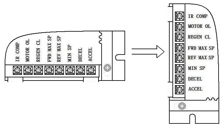
Introduction and setting of adjustable potentiometer:
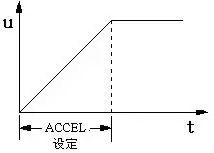
1. “ACCEL” potentiometer( Set soft start time ):
Adjust “ACCEL” potentiometer to set ramp up from initial speed value to setting speed value(it means acceleration time, the time can be adjusted between 0.2 seconds and 20 seconds).Please see the below Figure.
Note: Adjust this potentiometer in counter-clockwise to shorten soft start time while adjust this potentiometer in clockwise to prolong soft start time.
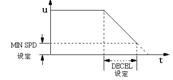
2. “DECEL” potentiometer( Set soft stop time ):
Adjust “DECEL” potentiometer to set ramp down from Max.speed value to Min.speed value(it means deceleration time, the time can be adjusted between 0.2 seconds and 20 seconds).Please see the below Figure.
Note: Adjust this potentiometer in counter-clockwise to shorten soft stop time while adjust this potentiometer in clockwise to prolong soft stop time.
3. “FWD MAX SP” potentiometer(set Max. forward speed value):
Adjust this “FWD MAX SP”potentiometer to set motor’s Max. forward speed value(it is also be used to limit motor’s Max. forward speed value). When adjust this potentiometer in clockwise, forward speed value is increased.
4. “REV MAX SP” potentiometer(set Max. reverse speed value):
Adjust this “REV MAX SP”potentiometer to set motor’s Max. reverse speed value(it is also be used to limit motor’s Max. reverse speed value). When adjust this potentiometer in clockwise, reverse speed value is increased.
5. “REGEN CL” potentiometer(set regenerative braking current value):
Adjust “REGEN CL” potentiometer to limit Max. braking armature current value(it also means brake/stop time). The braking current value affect brake/stop time. When adjust this potentiometer in clockwise, the braking current value will be increased.
6. “IR COMP” potentiometer(set torque compensation):
Adjust “IR COMP” potentiometer to make motor have constant speed value in different load conditions(Before the motor controller is delivered out of factory, the torque compensation generally set”0”). When adjust potentiometer in clockwise, torque compensation value is increased.
7. “MIN SP” potentiometer(set Min speed value):
When external given signal is “0V”(or adjust external signal setting potentiometer at end in counter-clockwise),adjust “MIN SP” potentiometer to set motor’s Min speed value(Generally this potentiometer is set “0”,before the motor controller is delivered out of factory).
8. “MOTOR CL” potentiometer(set motor’s rated current):
Adjust “MOTOR CL”potentiometer to limit motor controller’s Max.output current(we also says motor’s setting current value).The setting of this current should be based on motor’s rated current value.Current value should be moderate.If not,torque is not enough or overcurrent protection is failure. Adjust this potentiometer in clockwise to increase motor controller’s output current.
Note: Motor controller’s output current value should be twice as much as motor’s rated current value in general.However,motor controller can’t operate at setting value which is greater than motor’s rated current value for a long time, or the motor will be burnt out.
DC-4Q Braking-Reversible, DC controller, DC24RT100BL
This reversible dc controller has quickly dynamic response, smooth operating, works well and perfect functions. FOUR QUADRANT REGENERATIVE OPERATION
| Model | DC24RT100BL |
| Volt | 24VDC |
| Rated Continuous Current | 70A |
| Max current | 100A |
| Control Mode | 0-5V,PWM |
| Soft start time | 0.2-20S |
| Soft stop time | 0.2-20S |
| Tempreture | -10℃ - 60℃ |
| Protection grade | IP20 |
| Weight | 1.5kg |
| Dimension | 212*115*63mm |
| Suitalbe | PM Brush dc motor |
| Application | Electric vehicle,stereo garage,flaw detector |
Connection about speed control potentiometer:
The operation of speed control potentiometers should follow above instructions in below Figure. Fit 10K regulator potentiometer between 5V, IN and 0V.
Caution:
The connecting wire of speed control potentiometer should be away from conductors of power input terminal and output in sake for reducing unnecessary interfere of electronic signals. The length of connecting wire should be shorten as far as possible. If the length is over 0.5m, the shielding wire is recommended.
You also can control the motor speed by analog signal 0-5V, connect drawing as below:
Function and connection about control terminal:
Notice:
Connecting wires of speed control terminals should be away from conductors of power input terminal and output in sake for reducing unnecessary interfere of electronic signals. The length of connecting wire should be shorten as far as possible. If the length is over 0.5m, the shielding wire is recommended.
BRAKE:
Regenerative braking control: When quick stopping of motor is required, this function is suitable. Close brake switch, motor controller rapidly brakes motor’s speed by the way of regenerative braking then make motor stop immediately.
EN:
Enable control: Control the start and stop of motor
Open external enable switch, motor controller will automatically lock in internal circuit and make motor stops.
Close external enable switch,motor will start to rotate at the speed value set by potentiometer or input analog signals.
Note:
A.When regenerative braking, the motor’s stop time is decided by set value of brake current (“REGEN CL” potentiometer set current )or set value of soft stop (“DECEL” potentiometer set soft stop time).
Eg. If the set value of brake current(“REGEN CL” potentiometer set current ) is high and the set value of soft stop time(“DECEL” potentiometer set soft stop time) is low, the motor’s brake time will be shorten.
B.When close brake switch, rotate speed value after braking is decided by set value of “MIN SP” potentiometer (means Min speed ). Eg. If the “MIN SP” potentiometer set the value “0”, then after brake, the motor rotate speed will be “0”. If the “MIN SP” potentiometer set the value “N”, then after brake, the motor rotate speed will be “N”.
DIR: Reversing (Direction)control terminal:
The reversing control of motor: Rotation direction can be easily get through open or close reversing switch.
Introduction and setting of adjustable potentiometer:
1. “ACCEL” potentiometer( Set soft start time ):
Adjust “ACCEL” potentiometer to set ramp up from initial speed value to setting speed value(it means acceleration time, the time can be adjusted between 0.2 seconds and 20 seconds).Please see the below Figure.
Note: Adjust this potentiometer in counter-clockwise to shorten soft start time while adjust this potentiometer in clockwise to prolong soft start time.
2. “DECEL” potentiometer( Set soft stop time ):
Adjust “DECEL” potentiometer to set ramp down from Max.speed value to Min.speed value(it means deceleration time, the time can be adjusted between 0.2 seconds and 20 seconds).Please see the below Figure.
Note: Adjust this potentiometer in counter-clockwise to shorten soft stop time while adjust this potentiometer in clockwise to prolong soft stop time.
3. “FWD MAX SP” potentiometer(set Max. forward speed value):
Adjust this “FWD MAX SP”potentiometer to set motor’s Max. forward speed value(it is also be used to limit motor’s Max. forward speed value). When adjust this potentiometer in clockwise, forward speed value is increased.
4. “REV MAX SP” potentiometer(set Max. reverse speed value):
Adjust this “REV MAX SP”potentiometer to set motor’s Max. reverse speed value(it is also be used to limit motor’s Max. reverse speed value). When adjust this potentiometer in clockwise, reverse speed value is increased.
5. “REGEN CL” potentiometer(set regenerative braking current value):
Adjust “REGEN CL” potentiometer to limit Max. braking armature current value(it also means brake/stop time). The braking current value affect brake/stop time. When adjust this potentiometer in clockwise, the braking current value will be increased.
6. “IR COMP” potentiometer(set torque compensation):
Adjust “IR COMP” potentiometer to make motor have constant speed value in different load conditions(Before the motor controller is delivered out of factory, the torque compensation generally set”0”). When adjust potentiometer in clockwise, torque compensation value is increased.
7. “MIN SP” potentiometer(set Min speed value):
When external given signal is “0V”(or adjust external signal setting potentiometer at end in counter-clockwise),adjust “MIN SP” potentiometer to set motor’s Min speed value(Generally this potentiometer is set “0”,before the motor controller is delivered out of factory).
8. “MOTOR CL” potentiometer(set motor’s rated current):
Adjust “MOTOR CL”potentiometer to limit motor controller’s Max.output current(we also says motor’s setting current value).The setting of this current should be based on motor’s rated current value.Current value should be moderate.If not,torque is not enough or overcurrent protection is failure. Adjust this potentiometer in clockwise to increase motor controller’s output current.
Note: Motor controller’s output current value should be twice as much as motor’s rated current value in general.However,motor controller can’t operate at setting value which is greater than motor’s rated current value for a long time, or the motor will be burnt out.
