|
| Quantity: | |
|---|---|
220DP04BL
Keya
220DP04BL
I.Overview:
Jinan Keya PWM DC speed regulating system are the high-precision electronic speed-adjusting devices with the latest international digital control speed regulation technology and special parts. The device adopts international standard technical specifications with the technical indicators which meet international requirements of similar products. The device has a simple structure, small size, light weight, and other advantages, which can be used for pmdc motor. The pwm dc controller has multiple protection, security, stability and reliability. It can be fully compatible with similar international products, and has international quality and home-made prices.
II.Scope of application:
MMT series of DC motor speed controller are widely used in the machine tools, paper printing, textile printing and dyeing, fiber-optic cable equipment, packaging machinery, electrotechnical machinery, food processing machinery, rubber machinery, biological equipment, printed circuit board equipment, experimental equipment, welding cutting, light industry machinery, logistics transportation equipment, locomotives and rolling stock, medical equipment, communication equipment, and other industries.
III.Product performance
1. The mechanical characteristics of hardness, static error rate of 1%.
2. Wide speed-regulating range (0 - max).
3. Rapid dynamic response process.
4. Automatic smooth transition process during acceleration or deceleration.
5. Better excavator characteristics, can limit overload current to set value current.
6. High reliability and compact structure, high performance-price ratio.
IV.Characteristics of products
1. Speed regulation ratio 1:80 (Open loop)
2. Large moment at low speed operation
3. PWM pulse width modulation technology, low noise
4. Double closed loop PI regulation
5. Current settings, current limiting protection, over-current warning.
6. Setting function of soft starting and soft stop.
7. With fast response and good following.
8. Function of enabling block control.
9. Short current function.
V.Main Parameters:
1. Input Voltage:AC 110/220V±10%, depend on the controller label.
2. Output Voltage:DC 0~110V/220V or other voltage can be set.
3. Output Current:DC 4A
4.Rated Exciting Voltage/Current: DC 220V (110V) / 3A
5.Given signal model:potentiometer
6.The environment temperature: -10℃~+60℃
7.The environment Humidity: ≤ 80 RH relative humidity (Non-condensing)
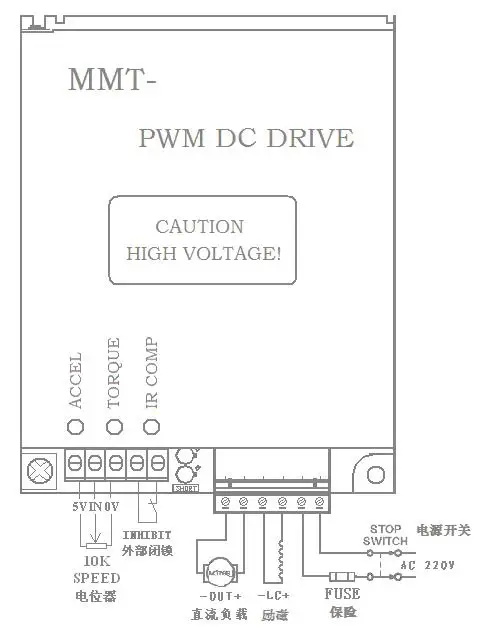
Instructions of terminal blocks
1. AC IN: Access AC power source input terminal
2. LC + -: exciting output(connected to motor exciting terminal, when use PMDC motor, don’t need connect LC+-)
3. OUT + -: Armature output (connected to motor armature)
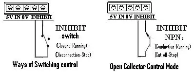
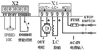
4. External enabling circuit block(INHIBIT): Enabling circuitry connecting - the control by a "enabling circuitry" to stop and open control (running when closed and stop when disconnected). Connect Switch to the terminal INHIBIT. See below figure.
Instructions on adjustment of internal potentiometer
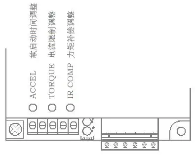
1.Current Setting/Limiting Adjustment: TORQUE
This potentiometer adjustment is intended for setting/limiting the max output current of the driving board according to the rated current of the motor. Through adjusting this potentiometer, the max output current can be up to 120%~200% of the motor rated current.
2.Torque Compensation Adjustment: IR COMP
IR COMP potentiometer is used to keep the motor speed constant when the motor working with different loads.
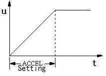
3.Soft Starting Time Adjustment: ACCEL
Through adjusting this potentiometer ACCEL, the upward slope from the starting speed to the preset speed can be defined (i.e. the time required to reach the preset speed, optionally between 0.3—10s).
Instructions of LED indicators:
1. POWER:Power normal instructions (Green)
2. TORQUE:Over current (Red)
When the output current of driver over "TORQUE" set value (see the first item in the adjustment instructions of potentiometer), the light is on (whether the driver stops output, please refer to the “Instructions on interpolation interface and plug-in selection”
Ways of reset: After troubleshooting, reset "INHIBIT" switch or reconnect driver’s power source.
3. SHORT: Short circuit protection instructions (Red)
When the driver "+ OUT -" output terminal has the external short-circuit, the drivers will quickly stop exporting, at the same time light “L2 over current / short circuit protection indicator”.
Reasons of reset: After identify the reasons and troubleshooting, re-connect driver’s power source.
Some actual connection example:
1. Conventional connection mode of one-way operation:
This kind of connection mode can use the "INHIBIT" can make switch control motor start or stop. see below figure.
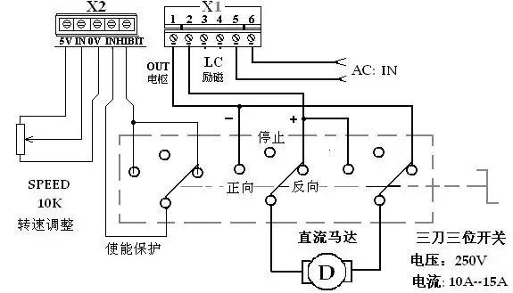
2. Example of wiring with simple forward/reverse reversing control mode:
This connection mode can be used to control the forward, stop, reverse of the motor by three poles three switches, as shown in below figure:
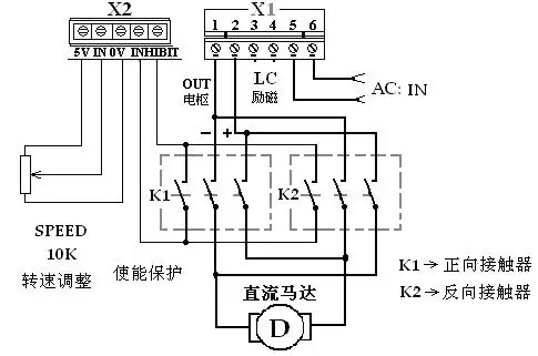
3. Example of contactor reversing connection:
This connection mode can be used for the linkage with other equipment or automatic control mode. As shown in figure.