|
| Quantity: | |
|---|---|
KYDAS4601A
Keya
KYDAS4601A
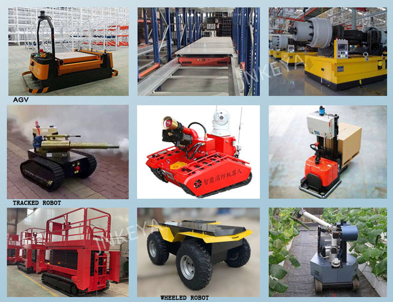
24-48V,60A,Intelligent Brushless DC Motor Controller KYDAS4601A, RS232, CAN open communicate, pwm rc radio analog signal control, it can control motor speed or position in close loop with 500ppr - 2500ppr optical encoder, It is suitable for the control of crawler robots, welcome service robots, medical robots, AGV intelligent handling robots, track and trackless electric flatbed vehicles, vegetable picking vehicles, and walking motors.
Scope of Application
Suitable for driving permanent magnet synchronous servo motor, low voltage AC servo motor.
Applicable motor: 24V 600W, 48V 1200W
Continuous current 30A, maximum peak current 60A over current protection time: 1s).DC working power +24~60V±10%.
Speed mode, torque mode, position mode;
Power supply
Rated working power: 24-60VDC.
Limit power supply range: 18--65VDC
It can provide instantaneous current overload capability of 2 times continuous current.
Feedback components
Incremental encoder
Absolute encoder (Should work with Keya motor)
Operating environment
Operating temperature: -25~55 °C (based on ambient temperature). Storage temperature: -35~65°C (based on ambient temperature).
Humidity: 5%--90%RH, condensation (25°C)
Protection level: IP22.
Insulation performance: input to the chassis DC600V, leakage current 0.07mA. The insulation resistance is 20 MΩ and more.
Three-proofing requirements: meet the requirements of three proofing (dust, moisture, salt spray).
Vibration requirements: frequency 5HZ ~ 25HZ, amplitude 3mm, 0.09g. 25HZ~200HZ, amplitude 1.47mm, 116g.Horizontal, vertical, and longitudinal directions for 30 minutes.
Cooling method: Built-in temperature control fan for cooling
Performance Index:
Working mode: speed mode, torque mode, position mode.
Feedback components: incremental encoder,absolute encoder,Hall sensor close loop feedback, magnetic encoder.
Control port: RS232, CAN 2.0, RC (Radio, model signal), 0-5V analog voltage,
Fault LED indication.
The controller have OUT output pin, delay control motor brake.
It can be controlled by CAN for parameter reading and monitoring.
Motor speed control and data reading through RS232.
Drive internal temperature monitoring.
Overcurrent and overload delay protection. Overvoltage and undervoltage protection.
Temperature protection.
Blocking and flying protection.
Motor short circuit protection
Note: Keep the controller away from dust and high temperature environment, and avoid unexpected contact. Keep sufficient space around the controller for ventilation and adjustment.
When fixing the controller, keep it from other heat sources. Ensure the controller works within the specified ambient temperature range. Avoid to install the controller to devices excessively vibrating; if it is necessary, please take good vibration-proof measures.
Technical parameters
| Parameter | Label | Parameter value | unit |
| Voltage | U | 24-60 | VDC |
| Maximum continuous current | Ic | 30 | A |
| Maximum peak current | I max | 60 (1s overcurrent protection) | A |
| PWM switching frequency | fPWM | 10 | kHz |
| Output encoder power supply | +5Vout | 5 | VDC |
| I CC | 100 | mA | |
Digital input | EN, DIR | Cutoff (high level): less than 1mA Conduction (low level): 3~7mA | mA |
| Digital output | Open collector | Maximum pull-up 48V, current 1A | |
| Analog input impedance | Single-ended input | 20 | KΩ |
| Analog signal voltage | Single-ended input | 0~5V | V |
RC signal control | Cycle 1.5ms | Motor stop | |
| 1.5ms - 2ms | Motor forward | ||
| 1.5ms-1ms | Motor revere | ||
Communication port | RS232 | 115200 | bps |
| CAN | 125/250/500 | Kbps | |
Encoder input | Signal property | 5V differential drive | |
| fmax | 200 | KHz | |
| Controllable speed range | RPM | 0~3000 | Rpm |
| Undervoltage protection | Vu | 18 | V |
| Temperature rise | T | 30A 30min≤35K | |
Operating temperature | Industrial grade (standard product) | -25 ~ +55 | ℃ |
| Military grade | -40 ~ +55 | ||
Storage temperature | Industrial grade (standard product) | -35 ~ +60 | ℃ |
| Military grade | -55 ~ +65 |
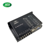
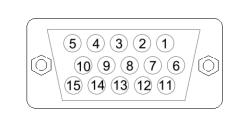
Control Port:
Hall and encoder interface definition:
| Pin | Function |
| 1 | Encoder A- |
| 2 | Encoder B+ |
| 3 | Encoder B- |
| 4 | Encoder Z- |
| 5 | Encoder Z+ |
| 6 | Encoder A- |
| 7 | Short |
| 8 | GND |
| 9 | RS-485/A |
| 10 | +5V |
| 11 | Temp |
| 12 | RS-485/B |
| 13 | Hall U+ |
| 14 | Hall V+ |
| 15 | Hall W+ |
Pin 7 and Pin8 can be short-circuited for program upgrade via external RS232 communication;
Pin 11: motor temperature input terminal, it can be used with GND, external temperature sensor 3950K-100K;
Pin 13,14,15: Hall U+,V+,W+ input;
Pin 1--6: encoder differential signal input pin;
Pin 9 and Pin 12: signal interfaces for absolute encoder;
Pin 10: +5V, it is be used for encoder power and Hall sensor power, with a maximum output current of 20mA;
Cotroll Interface description
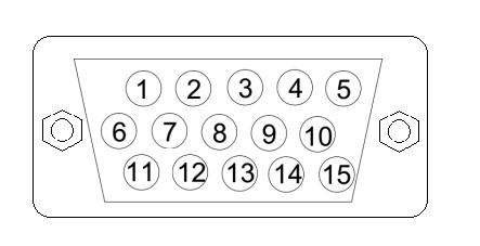
| Pin | Function |
| 1 | RS232-TX |
| 2 | Enable |
| 3 | F/R |
| 4 | GND |
| 5 | CAN-H |
| 6 | RS232-RX |
| 7 | SIN |
| 8 | SPI-MO |
| 9 | SPI-MI |
| 10 | CAN-L |
| 11 | GND |
| 12 | 5V |
| 13 | SPI-Set |
| 14 | SPI-CLK |
| 15 |
Pin 1, 6 and 11 are for the RS232 control ends, used for serial programming and serial control;
Pin 2: enable, active at low level
Pin 3 is for the Forward/Reverse, active at low level;
Pin 5 and 10 are respectively CAN bus interface, 250KHz; the internal matching terminal resistance (120R);
Pin 7 is for the analog signal input (0-5V);
Pin 12 is +5V, it can be used as analog quantity control, as the power supply for the high end of the potentiometer ;
SPI-terminal, used for magnetic encoder interface, or its communication data;
Pin 15 is for the RC signal input port: (when you use RC control, please connect Pin2(Enable) to GND at first)
Application