| Availability: | |
|---|---|
| Quantity: | |
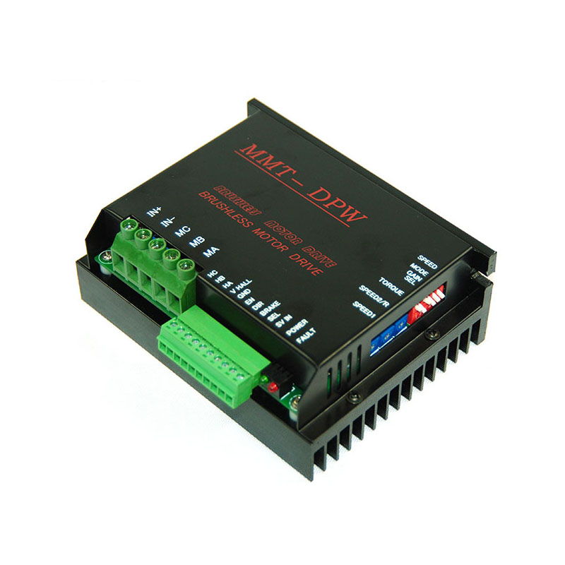
DC10/50DPW30BL
Keya
DC10/50DPW30BL
I: Features:
This controller has three manners of working: speed control, current control and open-loop control.
Control functions of braking, direction, enable, first-magnification, dual speed setting, etc. can be realized.
Maximum current limit can be adjusted.
0-5V signal control way for external potentiometer, interior potentiometer and external analog quantity and soft start function.
Time setting function for soft start.
Overcurrent protection function
Overheating protection function
When the temperature is too high, the speed controller will stop outputting and provide better safety for the moter and the speed controller.
High-speed control that full speed of one pole pair motor can reach 120000RPM
Details refer to relevant contents.
II: Performance Index:
1.Power supply voltage VCC: 10—50VDC (error <5% is better).
2.Maximum output voltage: Vout=0.95 X VCC.
3.Maximum output current: 30A.
4.Switching frequency: 39KHz.
5.Maximum speed (one pole pair motor): 120, 000rpm.
6.Hall power supply voltage range: 7—12VDC maximum output current is 30mA.
7.Locked-rotor protection time: 1.5 seconds.
8.Ambient temperature:
Working: -10-- +450C Storage: -20-- +600C
Ambient humidity range: 20—80%
9.Analog quantity output: 0-- +5VDC.
10.Soft start time: 20ms—10S.
11.Regulation voltage of external potentiometer : 0--+5V potentiometer (10KΩ/2W).
12.12. Overall dimension(including radiator): 127*48*92mm.
13.Weight: approximate 600g.
Specification and model:
| Model | Maximum Output current DC : (A) | Maximum Output voltage DC: (V) | Direct voltage Working range DC: (V) |
| DC10/50DPW30BL | 30 | 10-50 | 10-50(95%) |

VI: Wiring instruction on driver's terminals and schematic drawing of terminal functions: see Figure 2

Terminal 1:IN+ external connection with power positive pole.
Terminal 2:IN- external connection with power negative pole.
Terminal 3:MC motor winding C phase.
Terminal 4:MB motor winding B phase.
Terminal 5:MA motor winding A phase.
Terminal 6:HC motor HALL C phase.
Terminal 7:HB motor HALL B phase.
Terminal 8:HA motor HALL A phase.
Terminal 9:V HALL power positive pole, and HALL power voltage range:7—12VDC.
Terminal10:GND HALL area (common area).
Terminal11:EN Enable.
Terminal12:DIR direction selection.
Terminal13:BRAKE.
Terminal14:SEL assisted selection. ON for dial switch, the foot output is +5V conjunction with terminal 10 foot (GND) and terminal 15 foot(SV IN); while OFF for it, directed at two kinds of speed control ways as input port.
Terminal15:SV IN 0 -- +5V analog quantity input port conjunction with 10 foot(GND) and 14 foot (SEL).
I: Features:
This controller has three manners of working: speed control, current control and open-loop control.
Control functions of braking, direction, enable, first-magnification, dual speed setting, etc. can be realized.
Maximum current limit can be adjusted.
0-5V signal control way for external potentiometer, interior potentiometer and external analog quantity and soft start function.
Time setting function for soft start.
Overcurrent protection function
Overheating protection function
When the temperature is too high, the speed controller will stop outputting and provide better safety for the moter and the speed controller.
High-speed control that full speed of one pole pair motor can reach 120000RPM
Details refer to relevant contents.
II: Performance Index:
1.Power supply voltage VCC: 10—50VDC (error <5% is better).
2.Maximum output voltage: Vout=0.95 X VCC.
3.Maximum output current: 30A.
4.Switching frequency: 39KHz.
5.Maximum speed (one pole pair motor): 120, 000rpm.
6.Hall power supply voltage range: 7—12VDC maximum output current is 30mA.
7.Locked-rotor protection time: 1.5 seconds.
8.Ambient temperature:
Working: -10-- +450C Storage: -20-- +600C
Ambient humidity range: 20—80%
9.Analog quantity output: 0-- +5VDC.
10.Soft start time: 20ms—10S.
11.Regulation voltage of external potentiometer : 0--+5V potentiometer (10KΩ/2W).
12.12. Overall dimension(including radiator): 127*48*92mm.
13.Weight: approximate 600g.
Specification and model:
| Model | Maximum Output current DC : (A) | Maximum Output voltage DC: (V) | Direct voltage Working range DC: (V) |
| DC10/50DPW30BL | 30 | 10-50 | 10-50(95%) |

VI: Wiring instruction on driver's terminals and schematic drawing of terminal functions: see Figure 2

Terminal 1:IN+ external connection with power positive pole.
Terminal 2:IN- external connection with power negative pole.
Terminal 3:MC motor winding C phase.
Terminal 4:MB motor winding B phase.
Terminal 5:MA motor winding A phase.
Terminal 6:HC motor HALL C phase.
Terminal 7:HB motor HALL B phase.
Terminal 8:HA motor HALL A phase.
Terminal 9:V HALL power positive pole, and HALL power voltage range:7—12VDC.
Terminal10:GND HALL area (common area).
Terminal11:EN Enable.
Terminal12:DIR direction selection.
Terminal13:BRAKE.
Terminal14:SEL assisted selection. ON for dial switch, the foot output is +5V conjunction with terminal 10 foot (GND) and terminal 15 foot(SV IN); while OFF for it, directed at two kinds of speed control ways as input port.
Terminal15:SV IN 0 -- +5V analog quantity input port conjunction with 10 foot(GND) and 14 foot (SEL).