 |
| Quantity: | |
|---|---|
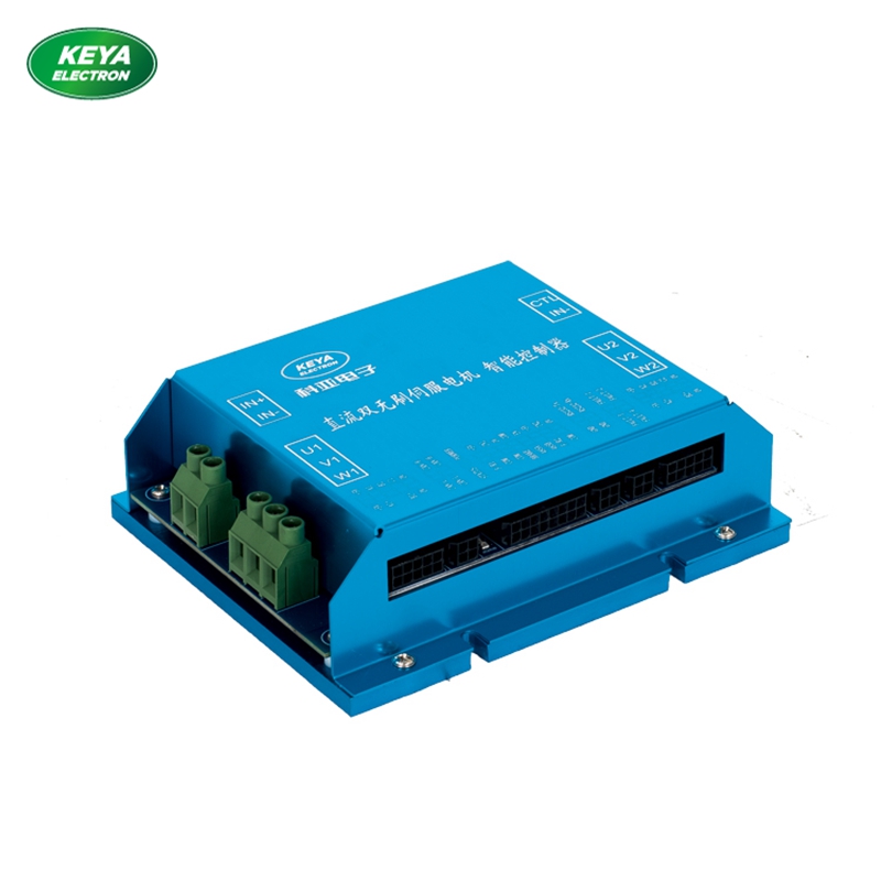
KYDBL4830-2E
Keya
KYDBL4830-2E
I. Overview
KYDBL4830-2E is an intelligent brushless DC dual channel motor controller. The brushless dual-channel motor driver can control two brushless DC motors at the same time. It adopts 32-bit high-performance MCU and advanced movement processing algorithm to realize internal electric differential function. The controller uses the Hall signal inside the motor as the rotor position feedback and works with the external incremental encoder (1000—2500 line) signal to control the movement of motor, realizing speed open-loop, close-loop modes, position mode and torque mode. It has two-way independent driver chip, two-way encoder processing chip, two-way Hall signal processing chip. Meanwhile, it has multiple failure alarm functions. It has two working modes: independent mode and mixed mode. Independent mode: It can realize fully independent control of two-way motor, and the control signal part is controlled by two-way input signals. Two-way brushless DC motor can control the speed and direction of motor, separately.
Mixed mode: It can realize the synchronous control (forward, backward, left and right rotation) of two brushless motors.
The control signal has as many as 8 modes (wireless remote control, rocker, potentiometer, analog quantity, frequency, pulse width, RS232, CAN bus).
II. Specification and Model
MODEL | MAX OUTPUT AMP AC : (A) | MAX OUTPUT VOLT DC:(V) | DC RANGE DC:(V) |
KYDBL4830-2E 30 55 0-55
III. Product Features:
* Wide-range voltage input, 10-55VDC.
* Intelligent PID control loop.
* Working mode: Speed open-loop, close-loop control, torque close-loop control, position close-loop control.
* External potentiometer, 0-5V analog quantity or pulse command control mode, RC (pulse width signal outputted by the receiver of aeromodelling remote control) control mode.
* Safety forward & reverse control, four-quadrant operation, support regeneration.
* Enable control function.
* Maximum current limit.
* 4-way input port; the function can be defined as analog input, pulse input or digital input functions.
* 6-way digital (MOS tube open-drain) output, which can serve as the failure alarm
status output of controller and can control the external relay to realize actions such as automatic disconnection of power.
* Abnormalities like over current, overheating, over voltage and short circuit will start the protection function.
* LED status indicator.
* CAN bus communication, see the detailed communication protocol when using it.
* RS232 communication, see the detailed communication protocol when using it.
IV. Performance Index:
1. Power voltage: 10-55VDC (voltage limit 5V-62V)
2. At the ambient temperature 25C, continuous working current 15A, transient current up to 30A 30S.
3. Minimum speed: 10 RPM in the speed close-loop mode; 1 RPM in the position mode.
4. Out +5VDC power (It can power up the encoder): 5V DC 20mA
5. Analog input range: 0-- 5VDC
6. Impulse input range: 500Hz—5000Hz (corresponding maximum speed)
[Note] The minimum impulse frequency may change along with the setting of maximum speed.
7. Input range of duty ratio 0%-- 100% (input frequency range f ≤ 1KHz, recommend to use the frequency of 250Hz).
8. Temperature protection status: When the temperature is 70C, the controller will reduce output by overheating protection and will stop output when the temperature is 80C.
9. Working temperature: -30C-- +60C.
10. Ambient humidity: Relative humidity≤80RH.
11. Boundary dimension: L * W * H = 142mm * 116.5mm * 34mm
11. Weight: 600g
V. Boundary Dimension:

Note: The bottom of controller shell has 4*Φ5mm holes for installation and fixing, and installation can be conducted in the horizontal direction.
Keep the controller away from dust and high temperature environment, and avoid unexpected contact. Keep sufficient space around the controller for ventilation and adjustment.
When fixing the controller, keep it from other heat sources. Ensure the controller works within the specified ambient temperature range.
Avoid to install the controller to devices excessively vibrating; if it is necessary, please take good vibration-proof measures.
VI. Description of Controller Terminal Wiring and Schematic Diagram of Terminal Function:


Description of connection terminals
1. Terminals IN+ and IN-
The left terminals IN+ and IN- are DC input (10-55V) and the right terminals are expansion ports, and they can not be used to input power.
2. Terminals U1, VI, W1
Output terminal, connected with brushless DC motor.
3. Hall/encoder signal input:
Adopts standard C3030WR-2*5P, 1-5 connect with the brushless motor Hall wire; 6-9 connect with the external encoder. The detailed definitions of interfaces are as follows:

Interface | Function | Remark |
| Controller output DC 5V (20mA) | |
| Brushless motor Hall wire---A1 | |
| Brushless motor Hall wire---B1 | |
| Brushless motor Hall wire---C1 | |
| 0V | |
| Controller output DC 5V (20mA) | |
| Encoder output phase A+ | |
| Encoder output phase B+ | |
| 0V |
4. Control port: Adopts standard C3030WR-2*8P.
Interfa ce | Function | Remark | Software I/O |
1 | 5V output | Control signal voltage | |
2 | Control Input IN1 | Analog/pulse input of Motor 1 | A/PIN1 |
3 | 0v | 0V | |
4 | com | COM | |
5 | Enable EN | Motor’s enable control | DIN3 |
6 | 5V output | Control signal voltage | |
7 | Control input IN2 | Analog/pulse input of Motor 2 | A/PIN2 |
8 | 0V | 0V | |
9 | F/R1 | Forward and reverse control of Motor 1 | DIN4 |
10 | COM | COM | |
1 1 | COM | COM | |
12 | BRAKE | Brake braking of Motor | DIN10 |
13 | |||
14 | |||
15 | F/R2 | Forward and reverse control of Motor 2 | DIN9 |
16 | COM | COM |
VII. Application


