 |
| Quantity: | |
|---|---|
KYDBL4875-2E
keya
III. Product Features:
* Wide-range voltage input, 10-55V, max limit voltage 60V.
* Intelligent PID control loop.
* Working mode: Speed open-loop, close-loop control, torque close-loop control, position close-loop control.
* External potentiometer, 0-5V analog quantity or pulse command control mode, RC (pulse width signal outputted by the receiver of aeromodelling remote control) control mode.
* Safety forward & reverse control, four-quadrant operation, support regeneration.
* Enable control function.
* Maximum current control.
* 4-way input port; the function can be defined as analog input, pulse input or digital input functions.
* 6-way digital (MOS tube open-drain) output, which can serve as the failure alarm status output of controller and can control the external relay to realize actions such as automatic disconnection of
power.
* Abnormalities like overcurrent, overheating, overvoltage and short circuit will start the protection function.
* LED status indicator.
* CAN bus communication, see the detailed communication protocol when using it.
* RS232 communication, see the detailed communication protocol when using it.
* USB communication, see the detailed communication protocol when using it.

Performance Index:
1. Power voltage: 10-55VDC.
2. At the ambient temperature 25℃, continuous working current 40A, transient current up to 75A 30S.
3. Minimum speed: 10 RPM in the speed close-loop mode; 1 RPM in the position mode.
4. Out +5VDC power (It can power up the encoder): 5V DC 20mA
5. Analog input range: 0-- 5VDC
6. Impulse input range: 500Hz—5000Hz (corresponding maximum speed)
[Note] The minimum impulse frequency may change along with the setting of maximum speed. 7. Input range of duty ratio 0%-- 100% (input frequency range f ≤1KHz, recommend to use the frequency of250Hz).
8. Temperature protection status: When the temperature is 70℃, the controller will reduce output by
overheating protection and will stop output when the temperature is 80℃.
9. Working temperature: -20℃-- +60℃.
10. Ambient humidity: Relative humidity≤80RH.
11. Boundary dimension: L * W * H = 190mm * 130mm * 77mm
12. Weight: 1000g
Boundary Dimension:
Note: The bottom of controller shell has 4*Φ5mm holes for installation and fixing, and installation can be conducted in the horizontal direction.
Keep the controller away from dust and high temperature environment, and avoid unexpected contact. Keep sufficient space around the controller for ventilation and adjustment.
When fixing the controller, keep it from other heat sources. Ensure the controller works within the specified ambient temperature range.
Avoid to install the controller to devices excessively vibrating; if it is necessary, please take good vibration-proof measures.

Description of connection terminals
1. Terminals IN+ and IN-
The left terminals IN+ and IN- are DC input ( 10-55V) and the right terminals are expansion ports,
and they can not be used to input power.
2. Terminals A, B, C:
Brushless DC motor controller output terminal, connected with brushless DC motor.
3. Hall/encoder signal input:
Adopts standard connector DR9, 1-5 connect with the brushless motor Hall wire; 6-9 connect with the external encoder
Interface | Function | Remark |
1 | Controller output DC 5V (20mA) | |
2 | Brushless motor Hall wire---A | |
3 | Brushless motor Hall wire---B |
4 | Brushless motor Hall wire---C | |
5 | GND | |
6 | Controller output DC 5V (20mA) | |
7 | Encoder A | |
8 | Encoder B | |
9 | GND |
4. Control port: Adopts standard DR25
Interface | Function | Remark | |
1 | 0V | 0 V | |
2 | Tx | RS232_Tx | |
3 | Rx | RS232_Rx | |
4 | Control input 1 | Analog/pulse input ofMotor 1 | P/AIN1 |
5 | GND | 0 V | |
6 | Control input 2 | Analog/pulse input ofMotor 2 | P/AIN2 |
7 | Enable control 1 | Enable control ofMotor 1 | DIN3 |
8 | Forward and reverse control 1 | Forward and reverse control of Motor 1 | DIN4 |
9 | Brake braking 1 | Brake braking of Motor 1 | DIN5 |
10 | Enable control 2 | Enable control ofMotor 2 | DIN6 |
11 | Forward and reverse control 2 | Forward and reverse control of Motor 2 | DIN7 |
12 | |||
13 | 5V output | Reference voltage of control signal | |
14 | 5V output | Reference voltage of control signal | |
15 | Brake braking 2 | Brake braking of Motor 2 | DIN13 |
16 | Failure alarm output terminal 1 | It can be set | DOUT 3 |
17 | Failure alarm output terminal 2 | It can be set | DOUT 4 |
18 | 0V | 0 V | |
19 | Failure alarm output terminal 3 | It can be set | DOUT 5 |
20 | Failure alarm output terminal 4 | It can be set | DOUT 6 |
21 | Failure alarm output terminal 5 | It can be set | DOUT7 |
22 | Failure alarm output terminal 6 | It can be set | DOUT8 |
23 | CAN-H | CAN-High | |
24 | CAN-L | CAN-Low | |
25 | 0V | 0V |
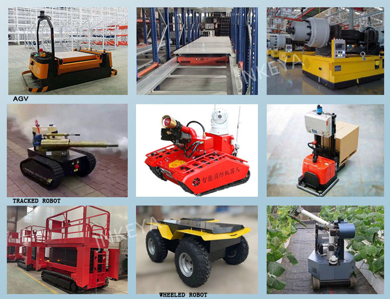
Application
If you have any question, please contact us any time.
Email: keya@jnky.com Tel: +8613255691051


