| Availability: | |
|---|---|
| Quantity: | |
KYDAS481601A
Keya
KYDAS481601A
I. Overview
1.1 Product specifications
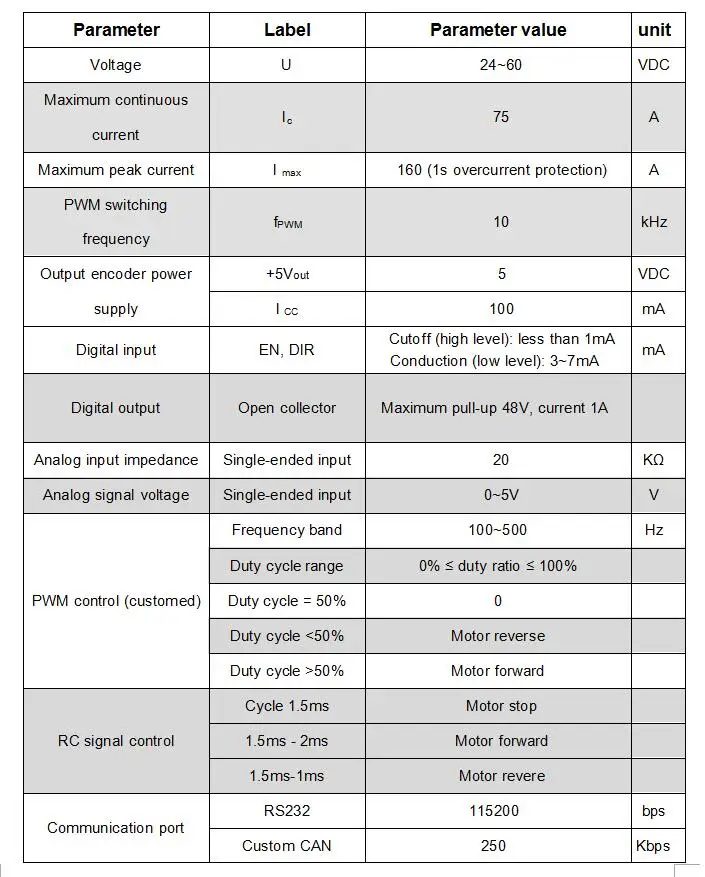
| Model:(Isolation type) | KYDAS41601A | ||
| RatedVoltage | 48VDC±10% (Note:If youneed72V~96V,productsneedtobecustomized) | ||
| Powerrequirement | The power supply must can absorb the back-emf, if not,needexternalabsorption device is required | ||
| Limitpower supply range | 35~72VDC | ||
| Rated Current | 80A±2% | ||
| Max Current | 160A±2% | ||
| Size(mm) | 208*202*78 | ||
| Matched motor | PMSM (permanent magnet synchronous servo motor) | ||
| Matchedpower | 2.3KW~3KW | ||
| Feedback | Incremental encoder;Magnetic encoder | ||
| IPgrade | IP54 | ||
| Cooling | Natural-cooled | ||
| Insulation | Input and output to the chassis DC600V,leakage current 0.07mA.Insulation resistance above 20MΩ | ||
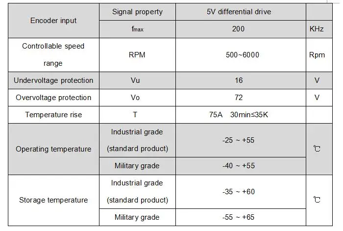
Environmental requirement | Working Temp | Industria | -20℃ ~ +55℃ |
| Military | -40℃~ +55℃ | ||
| Storage Temp | Industrial | -35℃ ~ +65℃ | |
| Military | -55℃ ~ +65℃ | ||
| Relative humidity | 0% ~ 90%RH、Condensation (25℃) | ||
| Vibration | Frequency 5HZ-25HZ,Amplitude 3mm,0.09g Frequency 5HZ-25HZ,Amplitude1.47mm,116g | ||
| Three proofings | Meet the three-proof requirements (dust,moisture,salt spray) | ||
| Main function | Working mode | Speed mode; Torque mode; Position mode | |
| Control way | RS232、CAN2.0、CANopen、RC,0-5V analog voltage | ||
| Protection | Overcurrent delay;Overvolts/Undervolts;Over temp; motor short circuit protection | ||
| Fault LED indication;Motor brake linkage | |||
Technical Index
2.1 Main function
Working mode: speed mode, torque mode.
Feedback components: incremental encoder (general product), Hall sensor close loop feedback, magnetic encoder.
Control port: RS232, CAN open, RC (model signal), 0-5V analog voltage, single-ended analog voltage (potentiometer).
External start and stop control.
Brake energy recovery function.
Fault LED indication.
It can be controlled by CAN open, RS232 for parameter reading and monitoring.
Motor speed control and data reading through RS232.
Drive internal temperature monitoring.
Overcurrent and overload protection. Overvoltage and undervoltage protection.
Temperature protection.
Blocking and flying protection.
Motor short circuit protection.
Back EMF bleed function (68V). if you power the controller with switching power supply or transformer power supply, please let me know in advance, we need to replace the discharge resistor.
2.2 Working mode configuration table


high power servo 24v 48v pmsm motor control foc control 150A

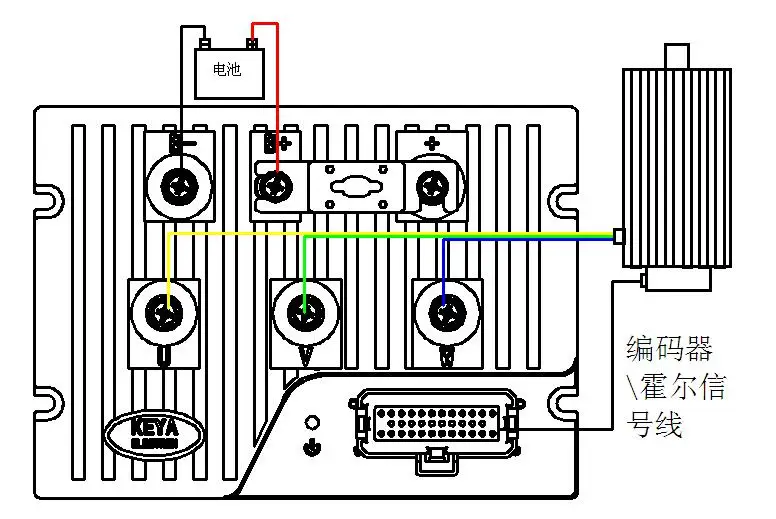
| B+ | Power supply + |
| B- | Power supply - |
| U | BLDC Motor - U |
| V | BLDC Motor - V |
| W | BLDC Motor - W |
Control Port:

| Pin | Function | Remark |
| 1 | CAN-L | CAN-L end |
| 2 | Encoder A- | Incremental encoder A- |
| 3 | Encoder Z+ | Incremental encoder Z+ |
| 4 | +5V | 5V output |
| 5 | ||
| 6 | OUT1 | Digital output 1 |
| 7 | SPI-SET | Magnetic encoder SPI-SET |
| 8 | SPI-SIMO | Magnetic encoder SPI-SIMO |
| 9 | GND | 0V |
| 10 | RX | RS232-RX |
| 11 | EN | Enable |
| 12 | F/R | Forward / Reverse |
| 13 | CAN-H | CAN-H |
| 14 | Encoder B+ | Incremental encoder B+ |
| 15 | Encoder Z- | Incremental encoder Z- |
| 16 | Hall W | Hall signal W+ (HC) |
| 17 | GND | 0V |
| 18 | ||
| 19 | SPI-SCK | Magnetic encoder SPI-SCK |
| 20 | SPI-SOMI | Magnetic encoder SPI-SOMI |
| 21 | RC | RC signal input |
| 22 | +5V | 5V output |
| 23 | AIN | Analog signal input (0-5V) |
| 24 | Encoder A+ | Incremental encoder A+ |
| 25 | Encoder B- | Incremental encoder B- |
| 26 | Hall U | Hall signal U+ (HA) |
| 27 | Hall V | Hall signal V+ (HB) |
| 28 | OUT2 | Digital output 2 |
| 29 | GND | 0V |
| 30 | +5V | 5V output |
| 31 | GND | 0V |
| 32 | TX | RS232-TX |
| 33 | +5V | 5V output |
| 34 | GND | 0V |
| 35 |
This driver be widly used in heavy agv, heavy automatic guided vehicle, tracked vehicle chassis, industrial robot chassis, robotic chassis, industrial robot platform, tank robot chassis etc.

I. Overview
1.1 Product specifications
| Model:(Isolation type) | KYDAS41601A | ||
| RatedVoltage | 48VDC±10% (Note:If youneed72V~96V,productsneedtobecustomized) | ||
| Powerrequirement | The power supply must can absorb the back-emf, if not,needexternalabsorption device is required | ||
| Limitpower supply range | 35~72VDC | ||
| Rated Current | 80A±2% | ||
| Max Current | 160A±2% | ||
| Size(mm) | 208*202*78 | ||
| Matched motor | PMSM (permanent magnet synchronous servo motor) | ||
| Matchedpower | 2.3KW~3KW | ||
| Feedback | Incremental encoder;Magnetic encoder | ||
| IPgrade | IP54 | ||
| Cooling | Natural-cooled | ||
| Insulation | Input and output to the chassis DC600V,leakage current 0.07mA.Insulation resistance above 20MΩ | ||
Environmental requirement | Working Temp | Industria | -20℃ ~ +55℃ |
| Military | -40℃~ +55℃ | ||
| Storage Temp | Industrial | -35℃ ~ +65℃ | |
| Military | -55℃ ~ +65℃ | ||
| Relative humidity | 0% ~ 90%RH、Condensation (25℃) | ||
| Vibration | Frequency 5HZ-25HZ,Amplitude 3mm,0.09g Frequency 5HZ-25HZ,Amplitude1.47mm,116g | ||
| Three proofings | Meet the three-proof requirements (dust,moisture,salt spray) | ||
| Main function | Working mode | Speed mode; Torque mode; Position mode | |
| Control way | RS232、CAN2.0、CANopen、RC,0-5V analog voltage | ||
| Protection | Overcurrent delay;Overvolts/Undervolts;Over temp; motor short circuit protection | ||
| Fault LED indication;Motor brake linkage | |||
Technical Index
2.1 Main function
Working mode: speed mode, torque mode.
Feedback components: incremental encoder (general product), Hall sensor close loop feedback, magnetic encoder.
Control port: RS232, CAN open, RC (model signal), 0-5V analog voltage, single-ended analog voltage (potentiometer).
External start and stop control.
Brake energy recovery function.
Fault LED indication.
It can be controlled by CAN open, RS232 for parameter reading and monitoring.
Motor speed control and data reading through RS232.
Drive internal temperature monitoring.
Overcurrent and overload protection. Overvoltage and undervoltage protection.
Temperature protection.
Blocking and flying protection.
Motor short circuit protection.
Back EMF bleed function (68V). if you power the controller with switching power supply or transformer power supply, please let me know in advance, we need to replace the discharge resistor.
2.2 Working mode configuration table


high power servo 24v 48v pmsm motor control foc control 150A

| B+ | Power supply + |
| B- | Power supply - |
| U | BLDC Motor - U |
| V | BLDC Motor - V |
| W | BLDC Motor - W |
Control Port:

| Pin | Function | Remark |
| 1 | CAN-L | CAN-L end |
| 2 | Encoder A- | Incremental encoder A- |
| 3 | Encoder Z+ | Incremental encoder Z+ |
| 4 | +5V | 5V output |
| 5 | ||
| 6 | OUT1 | Digital output 1 |
| 7 | SPI-SET | Magnetic encoder SPI-SET |
| 8 | SPI-SIMO | Magnetic encoder SPI-SIMO |
| 9 | GND | 0V |
| 10 | RX | RS232-RX |
| 11 | EN | Enable |
| 12 | F/R | Forward / Reverse |
| 13 | CAN-H | CAN-H |
| 14 | Encoder B+ | Incremental encoder B+ |
| 15 | Encoder Z- | Incremental encoder Z- |
| 16 | Hall W | Hall signal W+ (HC) |
| 17 | GND | 0V |
| 18 | ||
| 19 | SPI-SCK | Magnetic encoder SPI-SCK |
| 20 | SPI-SOMI | Magnetic encoder SPI-SOMI |
| 21 | RC | RC signal input |
| 22 | +5V | 5V output |
| 23 | AIN | Analog signal input (0-5V) |
| 24 | Encoder A+ | Incremental encoder A+ |
| 25 | Encoder B- | Incremental encoder B- |
| 26 | Hall U | Hall signal U+ (HA) |
| 27 | Hall V | Hall signal V+ (HB) |
| 28 | OUT2 | Digital output 2 |
| 29 | GND | 0V |
| 30 | +5V | 5V output |
| 31 | GND | 0V |
| 32 | TX | RS232-TX |
| 33 | +5V | 5V output |
| 34 | GND | 0V |
| 35 |
This driver be widly used in heavy agv, heavy automatic guided vehicle, tracked vehicle chassis, industrial robot chassis, robotic chassis, industrial robot platform, tank robot chassis etc.
